Overview
Buckle in, this may be a long post….
I have been working recently with a customer that happens to have a large vSAN environment – indeed, one of the largest vSphere clusters I have encountered at 48 hosts – and as a result I have been doing a good bit of thinking about how to give guidance for this customer, what sort of recommendations VMware should be providing, and generally how to approach fault domains in a vSAN environment.
In this post, I hope to address some of the design considerations for building out a vSAN cluster with fault domains beyond what is addressed in VMware’s vSAN Design and Sizing Guide. Nonetheless, if you are not already familiar with how to size a vSphere cluster to include vSAN storage, that is a great place to start, and required reading, as far as I am concerned.
Review of vSAN Cluster Basics
This is just a quick review of vSAN cluster basics in case you aren’t familiar with them. For further reading, be sure to read the vSAN Design and Sizing Guide.
- You need a minimum of 3 hosts to form a vSAN cluster – each host with a single disk group minimum.
- A disk group comprises a single SSD for caching, and 1 to 7 devices (SSD or HDD) for capacity.
- A host can have up to 5 disk groups (for a total of 5 cache devices and 35 capacity devices).
- The policies in vCenter will define protection and performance of the virtual machines on vSAN
- Failures to Tolerate (FTT) can be set to 1, 2, or 3.
- This indicates how many simultaneous drive or host failures any given virtual machine can tolerate or object (such as a VMDK), and impacts how many copies of data may exist on the cluster.
- Fault Tolerance Method (FTM) can be set to RAID1, RAID5, or RAID6.
- This defines layout of VMDK components across
- Rules for calculating required number of hosts:
- Where FTT=n, and FTM=RAID1…. Number of hosts = 2(n)+1
- Where FTT=n, and FTM=RAID5/6… Number of hosts = 2(n)+2
- Putting it together:
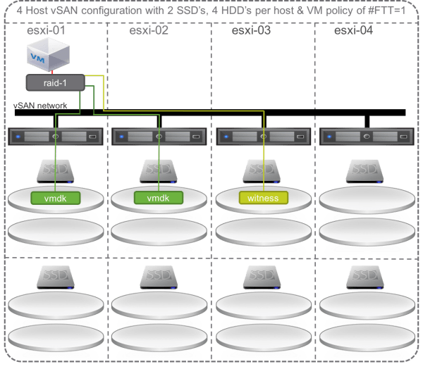
- If you apply a RAID1 policy to a virtual machine with FTT=1, its VMDK will be mirrored (2 copies plus a ‘witness’ for a total of 3 components) and spread across 3 hosts in the cluster.
- If you apply a RAID1 policy to a virtual machine with FTT=2, its VMDK will be mirrored twice (3 copies plus a 2 ‘witnesses’ for a total of 5 components) and spread across 5 hosts in the cluster.
- If you apply a RAID1 policy to a virtual machine with FTT=3, its VMDK will be mirrored three times (4 copies plus a 3 witnesses for a total of 7 components) and spread across 7 hosts in the cluster.
- If you apply a RAID5 policy to a virtual machine with FTT=1, its VMDK will be split up into 3 components (plus parity for a total of 4 components) and spread across 4 hosts in the cluster.
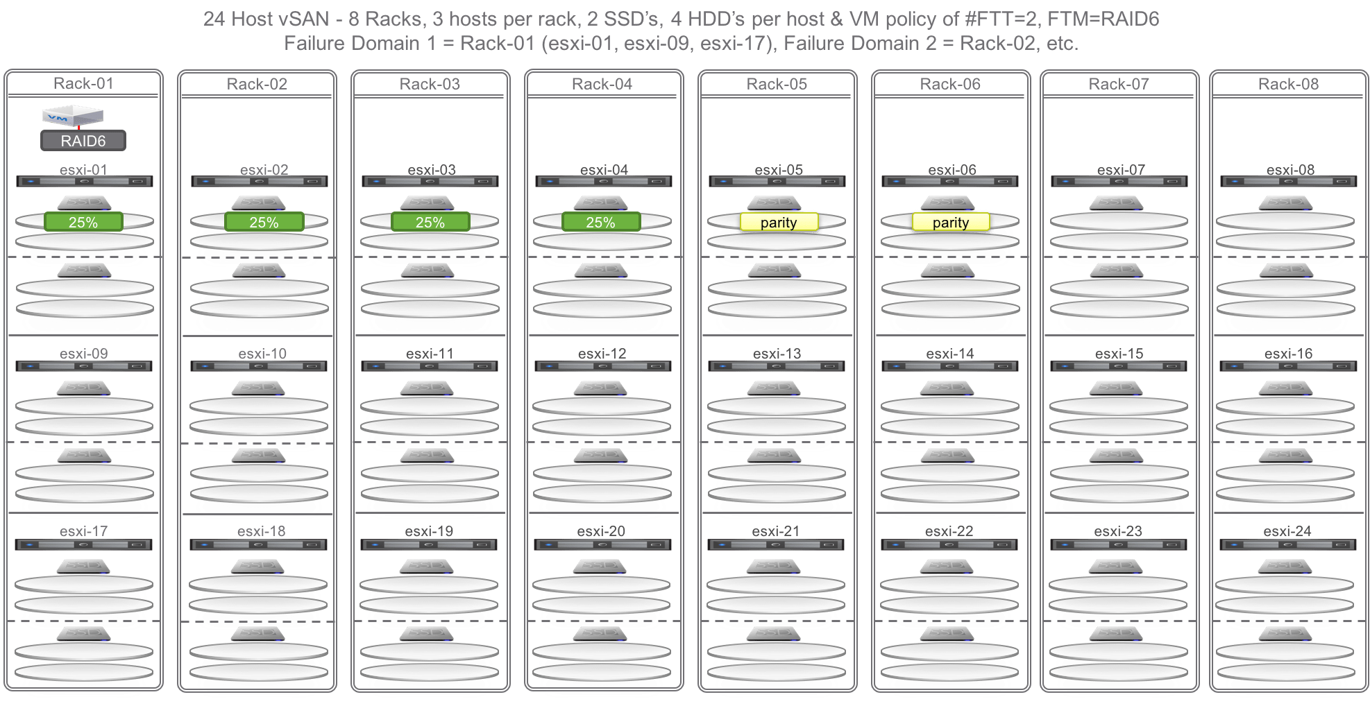
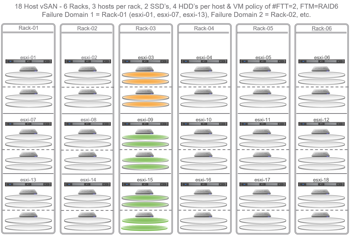
- If you apply a RAID6 policy to a virtual machine with FTT=2, its VMDK will be split up into 4 components (plus 2 parity for a total of 6 components) and spread across 6 hosts in the cluster.
- It should be noted that with vSAN 6.6 (vSphere 6.5 Express Patch 2), we can apply FTM/FTT policies to stretched clusters – with a ‘Primary’ setting for the overall cluster across sites, and a ‘Secondary’ setting for protection within a site.
vSAN Fault Domain Primer
For those not already familiar with vSAN Fault domains, it is necessary to review the default methodology vSAN uses to place virtual machine data upon a cluster. By default, in a new vSAN cluster each host is considered its own fault domain. This means that when a virtual machine is provisioned and its disk objects are created (VMDK, vSWAP, et cetera), the components of those objects will never be co-located on the same host. For example, assuming a single virtual machine, with a single VMDK file, and the storage policy set to FTT=1 / FTM=RAID1, the mirror copies of that VMDK file will be placed on separate hosts in the cluster. This is true even if those hosts have multiple disk groups – the copies of the VMDK will be spread across separate hosts.
Enabling Fault Domains, however, changes this behavior. Once fault domains are configured for the vSAN cluster, the components of a virtual machine’s VMDK file(s) will not only be distributed across hosts in the cluster, they will further never be co-located on hosts within the same fault domain (FD). For example, assuming a single virtual machine, with a single VMDK, and policy is set to FTT=2 / FTM=RAID6, the components of that VMDK file will be distributed across hosts in separate Fault Domains.
While this is straightforward in concept – and in implementation – there are major impacts to cluster design and planning, both in terms of architecture and capacity. Fault Domains may affect not only the amount of capacity in each host, but also the overall number of hosts.
Consider, for example, a scenario where all the hosts have two disk groups, and a capacity drive fails on a host. Normally, the impacted components would immediately be rebuilt on another drive, or potentially another host in the cluster, provided that host does not already house another component of the virtual machine (see the diagram below for an illustrated example).
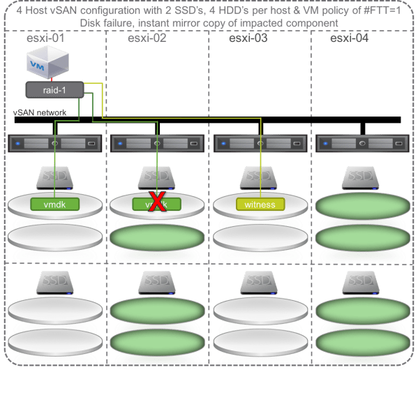
However, if Fault Domains have been configured, the rebuild of the impacted components is determined by the fault domains – the rebuild cannot occur on just any host, but must occur within the fault domain, or in another fault domain that does not already house a component of the impacted virtual machine.
Clearly this means that some additional arithmetic comes into play to ensure there is sufficient capacity within a fault domain for rebuild behavior, or sufficient capacity across fault domains to accommodate the required FTT and FTM settings in the policy applied to the virtual machine.
vSAN Cluster Fault Domain Design Considerations:
When building out a vSAN cluster, it is important to give consideration for exactly what the solution should provide in terms of availability and redundancy. This will affect the designed behavior of the solution. For the purposes of availability and redundancy, consider the following questions:
1 – What failure scenarios are you attempting to mitigate?
Obviously accommodating and mitigating the failure of drives is important, and also the failure of hosts. But what about other datacenter infrastructure? Top of Rack switching? Power distribution? Application components requiring distribution across disparate infrastructure? A single failure with regards to vSAN “Failures to Tolerate” (FTT) could be any one of the following – or even other components not listed below:
- A single capacity drive
- A single caching drive (and therefore the entire disk group)
- The drive or i/o controller (HBA, RAID controller, etc.- and therefore all disk groups attached)
- The vSphere host
- Power to the system
- Power to the rack
- Top of rack switch
- Other datacenter component affecting a vSphere host
- Other datacenter component affecting an entire fault domain
These are probably some of the most common failures (other than host or drive failures) to try to mitigate, and therefore also some of the most common reasons to create Fault Domains. Fault domains may correspond to one or more of those datacenter elements identified as potential points of failure.
Note: If attempting to mitigate a potential ‘site failure,’ consider either vSAN stretched clustering or vSphere Replication and VMware Site Recovery Manager.
2 – How many simultaneous failures are you willing to accommodate?
A single failure could be of any of the ONE elements above, a double failure could be any TWO of the above, and so on. The number of “Failures to Tolerate” should be the maximum number of simultaneous failures the solution should be able to accommodate, and will provide initial guidance for the number of vSAN clusters and Fault Domains.
Note: The maximum value of the “Failures to Tolerate” policy setting for vSAN is 3 when using mirroring, and 2 when using Erasure Coding. This applies to a single vSAN cluster. It may be possible to exceed these maximum failure tolerance levels if you include the use of stretched clustering, or application-level availability.
3 – What is your desired rebuild capacity?
While the solution may be able to tolerate multiple failures, it may not also be able to immediately rebuild data for them all… For example, tolerating the failure of an entire rack of infrastructure does not necessarily require the capacity to immediately rebuild that entire rack of infrastructure – one must weigh how likely the failure of an entire rack is against the cost of the additional rack of gear…
Note: For the purposes of calculating rebuild capacity, component failures, host failures, host maintenance, and even partial data evacuation capacity calculations are equivalent.
4 – What is your ‘maintenance tolerance’?
Finally, we must consider planned outages for normal operations such as upgrades, firmware updates, et cetera. It is normal to be able to take some number of hosts down for these operations, though when vSAN is serving as the primary storage of your cluster it may not be possible to take the entire cluster down for maintenance. Therefore, barring some extenuating circumstance that would require the outage of an entire cluster, the solution should be able to accommodate taking some number of hosts down for maintenance, or perhaps even an entire fault domain.
Note: For short maintenance windows, consider selecting “Ensure Accessibility” when placing vSAN hosts in maintenance mode. There is far less impact to the cluster due to the reduced need to migrate data, and if the maintenance window is only for a brief period of time, there is less risk of compared to a lengthier outage. Furthermore, due to the reduced need to migrate data, hosts may enter maintenance mode much more quickly.
The cluster should contain enough capacity so it has the ability to rebuild after a number of ‘tolerated’ failures, or to evacuate the desired number of hosts during maintenance procedures if that is the preferred operational practice. As it is not possible to ‘reserve’ hosts in a fault domain (or an entire fault domain) for these operations, it is easiest to plan for such capacity in one of two ways.
Failing Within the Fault Domain
Firstly, one could certainly take the approach of planning for maintenance or outages within a fault domain. In other words, for any given fault domain, plan for sufficient capacity to accommodate the outage of some number of nodes, and plan for the evacuated/impacted data to be ‘re-homed’ within the fault domain. This is a risk-averse, conservative approach. For example, if the solution requires 4 hosts per fault domain, but also requires the ability to take down 2 hosts within a fault domain, then either the remaining 2 hosts must carry 100% more capacity, or the solution must contain 6 hosts per fault domain. Furthermore, if the number of required fault domains is the same as the number of configured fault domains, then there must be sufficient capacity within the FDs to accommodate the maintenance activity planned. For example, if policy is set to RAID6, and there are only 6 fault domains, then any rebuilds or evacuation tasks must occur within the fault domain.
Failing Across Fault Domains
Alternatively, one could plan for maintenance or outages, but carry the spare capacity outside the affected fault domain. If the solution must accommodate the outage of 2 hosts, and there isn’t sufficient capacity within the impacted fault domains, the evacuated/impacted data must then be re-homed in a different fault domain. This implies that there are one or more fault domains that not only have available capacity, but aren’t already housing components of the impacted virtual machines. Clearly, this becomes somewhat more difficult to plan.
Luckily, the arithmetic necessary for understanding capacity requirements in the case of host / device failure, host evacuation, or data relocation for “Ensuring Accessibility” is the same for each.
Figuring it All Out
Calculating Base Cluster Capacity
As mentioned above, the vSAN Design and Sizing Guide is required reading for understanding the basics of how to size a vSAN cluster, and getting to a host configuration. This article will not review the guidance provided therein, but rather will focus on the additional tasks associated with understanding capacity planning for maintenance events in a vSAN cluster once fault domains have been configured.
However, it is a helpful exercise to first understand the basics of how to calculate capacity for maintenance events even if fault domains have not been configured. This is fairly straightforward arithmetic, and should be incorporated into cluster planning.

Using the figure above as a guide, and assuming the following configuration (note that dedup, compression, and vSwap overhead calculations have been omitted for simplicity):
- 24 hosts, each with
- (2) disk groups, each with
- (2) x 2TB capacity drives
- Totaling 8TB RAW per host
- 192 TB RAW for the cluster
- Less ~1% for VMFS overhead = 190 TB
- RAID6 consumption ratio of 1.5x
- 190TB / 1.5 consumption ratio = 126.67 TB useable
- 30% ‘slack’= 38 TB
- Remainder = 88.67 TB useable for virtual machines
- Per host:
- 8 TB Raw
- ~5.3 TB usable after RAID 6
- ~1.6 TB slack
- ~3.7 TB for virtual machines
vSAN Capacity Scenario 1:
A single host must be evacuated for maintenance. Datastore utilization is at 70%, meaning only the ‘slack’ space is available (3.7 TB used per host, as in above example).
If the intent is to tolerate the outage of a single host, the remaining 23 hosts must be able to ingest the host data. Therefore, one must calculate the amount of additional capacity the remaining 23 hosts must have available to successfully evacuate the single host for maintenance (or to tolerate its failure and rebuild):
Spare maintenance capacity may be calculated as follows:
- (1 host * 3.7 TB) / (24 total hosts- 1 maintenance host)
- (1*3.7)/(24-1)
- 3.7/23 = 0.161 TB or ~165 GB additional capacity per host
Clearly, in the scenario above, taking a single host down for maintenance may easily be accomplished with no concern, provided the 30% slack space is monitored and protected.
vSAN Capacity Scenario 2:
Eight hosts must be evacuated for maintenance. Datastore utilization is at 70%, meaning only the ‘slack’ space is available.
If eight hosts must be evacuated for maintenance, the remaining 16 hosts must be able to ingest the evacuated data. Therefore, we must calculate the amount of additional capacity the remaining 16 hosts must have available to successfully evacuate the single host for maintenance:
Spare maintenance capacity may be calculated as follows:
- (8 host * 3.7 TB) / (24 total hosts- 8 maintenance host)
- (8*3.7)/(24-8)
- 29.6/16 = 1.85 TB
Clearly in this scenario, the remaining 16 hosts require 1.85 TB free to ingest the evacuated data from the hosts in maintenance, yet they only have 1.56 free in slack space.
Note that we can capture this as the following formula, where:
- H= number of hosts in the cluster
- T= number of hosts to put into maintenance (or hosts to tolerate the failure of… your ‘Tolerance’ value)
- A= active data per host
Spare capacity required = (A*T/H-T)
To accommodate this action, one of the following would need to take place:
- more hosts would need to be added to the cluster
- greater than 30% slack space would need to be available
- all the hosts in the cluster would need an additional 1.8 TB spare capacity to accommodate the evacuation of up to 8 hosts.
Determining the Fault Domains
There are some straightforward guidelines for using vSAN Fault Domains one must remember that will materially impact the number of hosts, failover behavior, and capacity planning.
- There must be enough fault domains to meet or exceed the desired failure tolerance:
- Failures to Tolerate = 1 @ FTM= RAID1
- Will require a minimum of 3 fault domains
- Failures to Tolerate = 1 @ FTM= RAID5
- Will require a minimum of 4 fault domains
- Failures to Tolerate = 2 @ FTM= RAID1
- Will require a minimum of 5 fault domains
- Failures to Tolerate = 2 @ FTM= RAID6
- Will require a minimum of 6 fault domains
- Failures to Tolerate = 3 @ FTM= RAID1
- Will require a minimum of 7 fault domains
- Failures to Tolerate = 1 @ FTM= RAID1
- The minimum number of fault domains is determined by the SPBM policy requiring the greatest number of hosts to meet the policy.
- Remember that all this is determined by policy, and multiple policies may be in use. For example, if all three of the following policies are in use:
- a RAID 6 policy to some virtual machines
- a RAID 5 policy to other virtual machines
- a RAID 1 policy to still others
- A minimum of 6 fault domains must be implemented to satisfy the RAID 6 policy.
- Remember that all this is determined by policy, and multiple policies may be in use. For example, if all three of the following policies are in use:
- At least 2 vSAN hosts should exist in each fault domain… otherwise why create them?
- Fault domains should have a balanced configuration with an equal number of hosts per FD – failure to do so may create a situation where some fault domains fill more quickly than others, creating undesirable rebalance operations.
- For example, if 10 hosts are required to service the workloads (CPU and RAM), but a RAID6 SPBM policy is desired, a minimum of 12 hosts (6 fault domains with 2 hosts each) should be configured for the environment.
- There should be a strategy and an operational run book for how maintenance will be performed for the environment… Plan for one of the following:
- If the number of configured Fault Domains is equivalent to the required Fault Domains as indicated by policy, sufficient capacity must be maintained within each fault domain to evacuate the desired number of hosts during maintenance.
- If the number of configured Fault Domains exceeds the required Fault Domains as indicated by policy, then either:
- Sufficient capacity must be maintained within each fault domain to evacuate the desired number of hosts during maintenance. OR
- Sufficient capacity must be maintained in the excess Fault Domain(s) to evacuate the desired number of hosts during maintenance.
Calculating Capacity Tolerance – Within the Fault Domain
If the number of configured Fault Domains is equivalent to the required Fault Domains as indicated by policy, there is no choice but to burden the hosts within the fault domains with the extra capacity. Therefore capacity calculations must include the amount of spare capacity the hosts within the fault domain must have to ingest the data from the host(s) in maintenance mode.
Spare capacity may be calculated as follows, where:
- D= number of hosts in Fault Domain
- T= number of hosts to put into maintenance (or hosts to tolerate the failure of… the ‘Tolerance’ value)
- A= active data per host
(Active data per host x Number of hosts to put into maintenance)
divided by
(number of hosts in the fault domain – hosts to be put in maintenance mode)
(A*T/D-T)
For example:
- (3.7 TB * 1 host) / (3 hosts in FD – 1 host)
- 3.7/(3-1)
- 3.7/2
- 1.85 TB spare capacity required per host in the FD
on each of the remaining hosts after taking 1 down
Calculating Capacity Tolerance – Across Fault Domains
If the number of configured Fault Domains exceeds the required Fault Domains as indicated by policy, and there is insufficient capacity within the fault domain to ingest evacuated data, it is possible to burden the additional fault domains with the extra capacity. Therefore capacity calculations must include the number of available or extra fault domains, and determine the amount of spare capacity the hosts in those fault domains must have to ingest the data from the hosts in maintenance mode.
Spare capacity may be calculated as follows, where:
- F= number of total Fault Domains
- R= number of required fault domains to satisfy policy
- D= number of hosts in Fault Domain
- T= number of hosts to put into maintenance (or hosts to tolerate the failure of… your ‘Tolerance’ value)
- A= active data per host
(Active data per host x Number of hosts to put into maintenance)
divided by
(total fault domains – fault domains required) x (number of hosts in each fault domain)
(A*T) / ((F-R)*D))

For example:
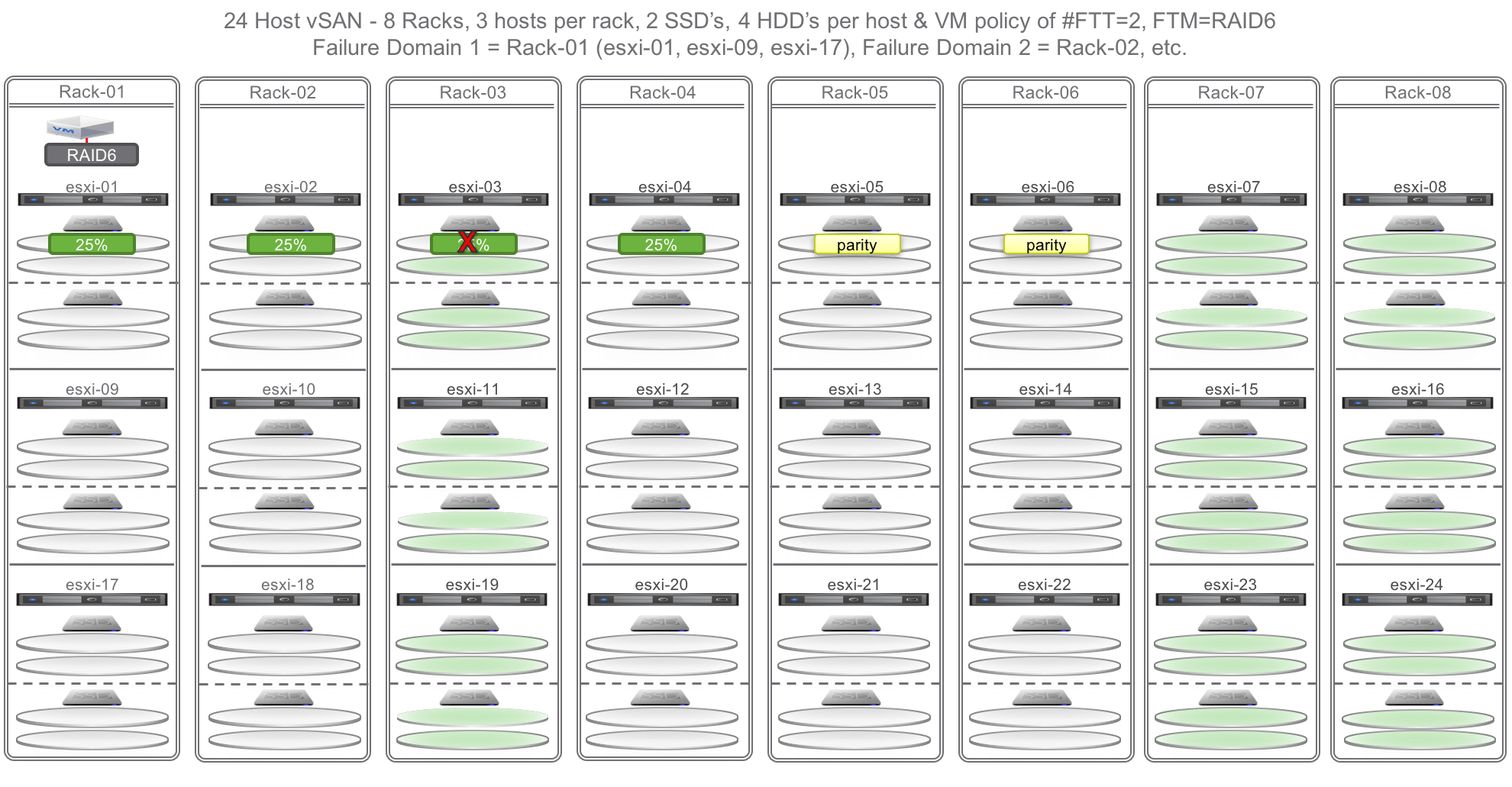
Using the image above as an example, to be able to take 3 hosts down for maintenance, yet still have enough capacity to rebuild impacted data in the event of a host failure in Fault Domains 7 & 8 – and still using a figure of 3.7TB of active data per host – capacity may be calculated as follows:
- (3.7 TB * 3 hosts) / ((8FD total – 6FD required)*3 hosts per FD)
- (3.7*3)/((8-6)*3)
- 11.1/(2*3)
- 11.1/6
- 1.85 TB spare capacity required on each of the 6 hosts in the remaining 2 FD to evacuate FD #3
Quick Recap
Having worked through the examples above, we see that the arithmetic for understanding capacity requirements in either the case of tolerating host failures or evacuating data (all or some) is the same for both, but differs slightly depending on your architecture and strategy.
Maintenance / Failures Without FD:
- H= number of hosts in the cluster
- T= number of hosts to put into maintenance or hosts to tolerate the failure of= Tolerance
- A= active data per host, or data to be migrated
- Spare capacity required = (A*T/H-T)
Maintenance/Failure Within FD:
- D= number of hosts in Fault Domain
- T= number of hosts to put into maintenance or hosts to tolerate the failure of= Tolerance
- A= active data per host, or data to be migrated
- Spare capacity required = (A*T/D-T)
Maintenance/ Failure Across FD:
- F= number of total Fault Domains
- R= number of required fault domains to satisfy policy
- D= number of hosts in Fault Domain
- T= number of hosts to put into maintenance or hosts to tolerate the failure of= Tolerance
- A= active data per host, or data to be migrated
- Spare capacity required = (A*T) / ((F-R)*D))
Conclusion
The use of Fault Domains in a vSAN cluster has the potential to mitigate the failure of datacenter components that might otherwise place your vSAN-protected data at risk. As demonstrated above, however, configuring Fault Domains in a vSAN cluster can have a material impact on capacity planning for both rebuild activities as well as maintenance activities. Care must be taken to plan out what failure scenarios will be accounted for, as well as the number of hosts that might be placed in maintenance mode concurrently. Customers should closely monitor the available capacity not only on the entire cluster, but also within each Fault Domain, host, and disk group to be sure resources remain balanced for optimal operations.
Postcript
Iwan Hoogendoorn (@i1wan) recently wrote a blog article in which he discusses stretched vSAN clusters and fault domains as part of a highly-available SDDC design, leveraging VMware NSX as well. As part of his work, he also developed an Excel worksheet he uses to calculate vSAN capacities for production and maintenance purposes, based on my discussion above.
You can check out his blog here: http://www.iwan.wiki/Running_NSX_on_top_of_vSAN_(with_vSAN_Calculator_in_Google_Spreadsheet)

Outstanding technical layout of your vSAN cluster and fault domains.
Now I have a situation whereby customer has 342 hosts. These are going to be built with the latest vSAN 6.6 on ESXi 6.5 latest build and managed by vCenter 6.5 with latest build. How do l even design a fault domain? Each host has 2*400GB SSD and 6 *960 HDD – all flash. Customer wants FTT=2
Well, there are few things to keep in mind, of course… a vSAN datastore is constrained to a single cluster, and of course a vSphere cluster can grow to a maximum of 64 hosts, so you already are into multiple clusters. The first thing I would decide on is how many clusters, and whether or not you would like to distribute the hosts in each cluster across multiple racks or not.
FTT=2 may be accomplished with either FTM=RAID1 or RAID6, the difference being in the amount of capacity consumed, as well as overall iops required to support the selected FTM.
Once you have decided upon the desired FTM, distribution of hosts across racks, and operational boundaries that may impose limits on cluster size, then you can begin to think about whether you want to use fault domains, how many FD you will need for each cluster, and the number of hosts per FD.
Well Written your 24 node cross rack, fault domain was what I have in my head for 32 node cluster. Well with one more host 🙂
The VMware Technical Marketing has just incorporated some of this guidance into the official Design and Sizing Guide here – https://storagehub.vmware.com/t/vmware-vsan/vmware-r-vsan-tm-design-and-sizing-guide/fault-domains-9
Well written with deep example